Single-Pass Tangential Flow Filtration Implementation and Scaling
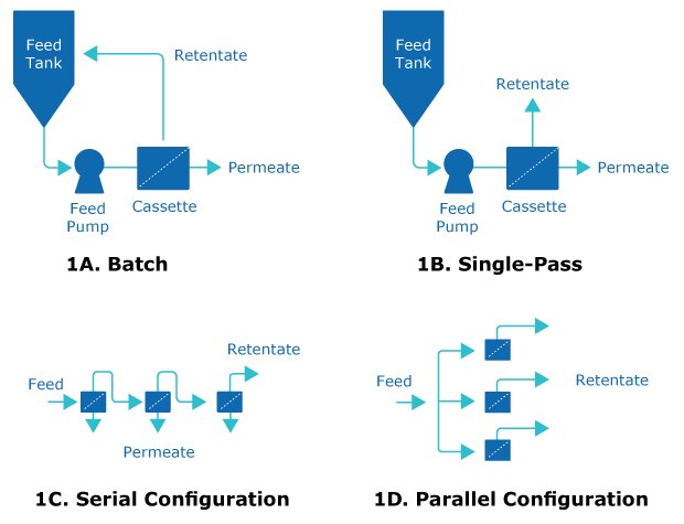
Figure 1.Comparison of traditional TFF (1A) with single-pass TFF (1B). Conversion increases with residence time with a serial feed channel configuration (1C) over a parallel configuration (1D) due to higher flow velocities and mass transfer. Permeate is not shown in 1D.
Tangential flow filtration (TFF) is used in downstream processing to concentrate product and exchange buffers. It typically operates in batch mode and requires several passes through a TFF filter assembly (Figure 1A).
An alternative: single-pass tangential flow filtration (SPTFF). In SPTFF, the feed is concentrated after just one pass through the filter, eliminating the need for retentate recycling (Figure 1B). The basic principle underlying SPTFF is that increased residence time in the feed channel results in increased conversion. Increased residence time can be accomplished by reducing flow rate or increasing path length in a serial configuration (Figure 1C). Configuring TFF cassettes or capsules in series can improve conversion. TFF filters in series have a higher mass transfer when compared to parallel configurations at equivalent residence times (Figure 1D). Learn more about the different types of TFF in our technical article.
Single-Pass Tangential Flow Filtration Implementation
Implementing SPTFF using Pellicon® Capsules in your process requires three basic steps:
- Setting up the filter assembly by installing the Pellicon® Capsules in series
- Establishing operating conditions by (a) determining the optimal retentate pressure at a baseline test flow rate and (b) conducting feed flux excursions to obtain target conversion
- Confirming stability by conducting a single-pass process simulation at the target conversion
Installing Pellicon® Capsules
The Pellicon® Capsules are first configured with the target number of sections (capsules installed in series), typically three sections where each section must be of equal area for a full exploration of the process window. It is recommended that the system is configured in total recycle mode (retentate and permeates returned to feed tank) to minimize feed volume required during extended run time when setting operating conditions. The retentate of the first capsule in series will be connected directly to the feed of the second and subsequently alternated for each additional capsule in series. This configuration will create the elongated feed channel.
Establishing Operating Conditions
To find the optimal retentate pressure, the feed flux is typically set to 1 LMM (liters/min per m2) and the conversion is monitored starting from lowest retentate pressure (e.g. retentate valve fully open), which is then increased incrementally until the maximum desirable conversion is reached, the system becomes hard to control or unstable, or the flux stops increasing. The endpoint will depend on your application. Before setting final operating pressure conditions, it is important to allow sufficient time for the polarization to fully develop and flux to stabilize—stabilization time range is generally 1–30 minutes, depending on protein concentration and other process conditions and is indicated by stable pressure readings.
The retentate pressure is increased in small increments (e.g. 1–2 psi) until an inflection in the curve is observed (Figure 2). If the retentate valve is completely shut off or TMP extends too far into the plateau region, the membrane will foul. In the example shown in Figure 2, the ideal pressure setpoint is around 2 psi for the 0.1 m2 Pellicon® Capsule and 5 psi for the 0.11 m2 Pellicon® 3 cassette. At this setpoint combination, there is an equivalent conversion between the device formats and tolerance for small changes in retentate pressure.
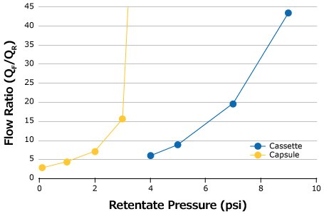
Figure 2.Example of optimal pressure curves for 1 g/L feed at 1 LMM.
Once an optimal retentate pressure is found, it must be kept consistent throughout the experiments but can be confirmed once the desired feed flow rate is established to ensure a robust process. Note that more dilute feeds generally require lower retentate pressure for a given conversion.
Feed flux excursions are then conducted using the established optimal retentate pressure and starting at 1 LMM (depending on desired conversion, the operator may choose to run at higher feed flow rates if conversion is too high at 1 LMM). For a 3-section series, the whole assembly is run, and individual permeate flows are recorded to calculate conversion for each section: 1 section, 2 sections (sections 1 and 2), and 3 sections (sections 1 through 3), at the different feed flow rates. The feed flow rate for the process is determined based on the required conversion and number of sections. This will vary from process to process depending on the desired outcome. This data is plotted to reveal the optimal feed flow rate for operation at the desired conversion.
Confirmation of Stability
Using the selected operating conditions and number of sections, stability is confirmed by conducting a single-pass process simulation. At this point, it is recommended to start with fresh feed material.
After equilibration, the feed is pumped through the capsule SPTFF assembly at the determined optimal conditions until the conversion and pressure profile become steady. This can be done in single-pass mode or in total recycle mode if there is insufficient feed volume. Stabilization time will depend on feed conditions and chosen feed flow rates. Note that initial dilution may be needed if steady state operation is achieved via single-pass mode. This process should take between 1 and 30 minutes but can vary outside this range. Once stable, the retentate is collected in single-pass mode and the conversion is monitored over the target run time.
Case Study 1: Pellicon® Capsule vs Pellicon® 3 Cassette on Bovine gamma Globulin (BgG)
Bench-scale studies were carried out to evaluate the effectiveness of Pellicon® Capsules 0.1 m2 for use in SPTFF operation compared to Pellicon® 3 cassettes 0.11 m2. A bovine gamma globulin (BgG) solution was used as a model antibody feed. The capsules and cassettes were run side-by-side in SPTFF mode. In each case, the optimal retentate pressure was determined before running feed flux excursions and a final conversion stability study was conducted.
Optimal retentate pressure determinations were carried out on both the Pellicon® Capsule and Pellicon® 3 cassette SPTFF setups for 1 g/L and 25 g/L BgG feeds using the methodology described above. The ideal retentate pressure setting is lower for the lower feed concentration. This is an important note as feed conditions have a direct impact on the performance of the SPTFF operation and should be checked if there is a change in feed composition. In addition to the change associated with feed, it can also be seen from the data in Figure 3 that there is a different retentate pressure requirement between the capsule and cassette. Yet, as described in Scalability of SPTFF Capsules and Cassettes (below), maintaining pressure drop and feed flux will allow the conversion to remain consistent between both filter formats.
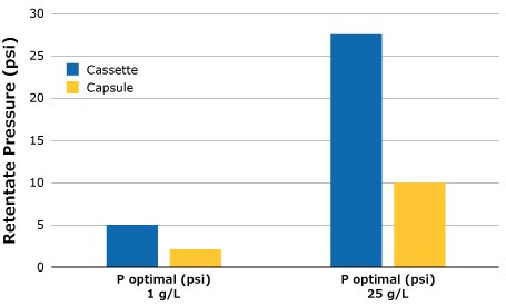
Figure 3.Optimal retentate pressure for SPTFF setups, 3 in series.
Feed flux excursions were completed for the 25 g/L feed solution at the established optimal retentate pressures starting at a feed flux of 1 LMM and decreasing at desired intervals to 0.14 LMM. The feed flux curves for the 25 g/L feed solution are compared in Figure 4. Although the highest conversion was achieved at 0.14 LMM by the third capsule for 0.1 m2 capsules, the plotted data points of both cassette and capsule formats depict comparable performance over the course of the feed flux excursions.
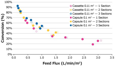
Figure 4.Feed flux excursion for 25 g/L BgG feed solution.
Following the feed flux evaluation, a stability study was completed to demonstrate process stability and overall conversion for each system. For this run, the flow rate that gave the highest conversion was chosen (0.14 LMM) to demonstrate robustness at the most challenging setpoint. As seen in the feed flux curves in Figure 5, it was anticipated that the capsule would produce a slightly higher overall conversion than the cassette. This was confirmed by the stability study (Figure 5).
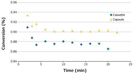
Figure 5.Process stability for SPTFF of 25 g/L BgG run at 0.14 LMM.
Based on the experimental results and findings, similar performance can be expected when switching between Pellicon® Capsule and Pellicon® 3 cassette for SPTFF operations. Feed conditions do play a significant role, especially at the low feed concentrations; therefore, it is important to check for optimal retentate pressure, particularly if switching between cassette and capsule formats.
Scalability of SPTFF Capsules and Cassettes
Scaling to or from a 0.1 m2 Pellicon® Capsule to either another capsule size or a Pellicon® Cassette can be easily achieved by keeping the feed flux (set by the pump) and pressure drop across the feed channel (set by retentate valve at the given feed flux) the same between scales. This will result in a new optimal retentate pressure setpoint. Alternatively, the optimal retentate pressure can be re-established from scratch at the new scale.
For ease-of-use, the former method is recommended, where the same feed channel pressure drop is maintained across scales. By maintaining pressure drop and feed flux, the conversion will remain consistent. The capsule will scale within its own family or to cassettes without the need to re-establish the optimal retentate pressure.
Case Study 2: Pellicon® Capsule Scaling Study on mAb from 0.1 m2 to 0.5 m2 Scale-Down Study
Scale-Down Study
The purpose of the experiment was to determine optimal operating conditions for the pilot-scale operation. Scaling studies from 0.1 m2 to 0.5 m2 Pellicon® Capsule were carried out using clarified harvest fluid from an in-house mAb expressing CHO cell culture at a starting mAb concentration of approximately 1.3 g/L. On the day of the harvest, 2 liters of clarified feed were run at 0.1 m2 scale in a 3-section (3 × 0.1 m2) SPTFF capsule system.
Using the methodology described in Case Study 1, the optimal retentate pressure was established for the mAb feed solution at a feed flux of 1 LMM. The retentate pressure setpoint was determined to be 4 psi and was held constant throughout the subsequent feed flux excursions.
Starting at approximately 1 LMM and continuing at decreasing intervals, a series of feed flux excursions were carried out. The goal was to determine the conditions for a 90% conversion (10x concentration factor). Turbidity data and measured concentration were plotted alongside the predicted concentration curves. The plot in Figure 6 shows the output for the series of experiments as a function of concentration, predicted mathematically by the conversion obtained and confirmed with PrA HPLC assay measurement.
The measured values marked as “×” show agreement between predicted and actual measured data. For a target conversion of 90% (final concentration ~13 g/L), the required feed flux with 3 capsules in series was determined by simply identifying the resultant x axis value at the target concentration. Hence, a feed flux of 0.84 LMM was chosen for processing the full volume of approximately 70 L.
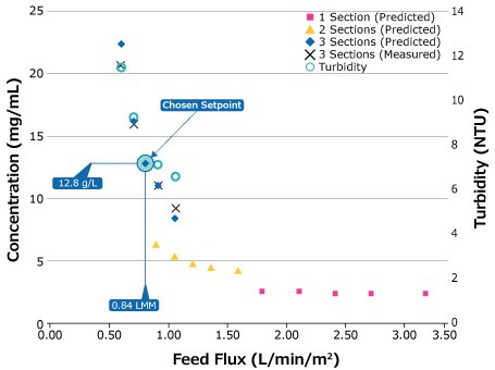
Figure 6.Results of 0.1 m2 capsule, 3-section series SPTFF scale-down study.
Scale-Up Study
For the pilot run, three 0.5 m2 Pellicon® Capsules were arranged in series, flushed, and equilibrated with buffer prior to processing. The feed pump was set to 0.84 LMM to match the optimal feed flux determined from the scale-down system. For this experiment, the retentate was not returned to the feed vessel for a stabilization period: retentate and permeate were both collected in vessels on scales and measured at regular intervals throughout the run to monitor process stability.
Retentate pressure was initially set at 4 psi and manually increased to 13 psi to match the feed channel pressure drop from the scale-down study and hit the desired conversion. Much like the pressure differences seen between the Pellicon® Capsule 0.1 m2 and Pellicon® 3 cassette 0.11 m2, pressure differences are seen between the 0.1 m2 and 0.5 m2 capsules (Figure 7). For the 0.1 m2 capsule only, less pressure is needed to achieve the desired conversion. However, when comparing pressure drop between the different capsule sizes, the values are the same.
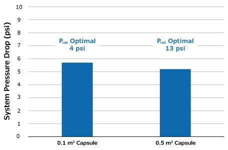
Figure 7.Pressure drop across feed channel for 0.1 and 0.5 m2 capsules at 0.84 LMM.
Once stability was achieved, the process ran uninterrupted for approximately 1 hour at consistent concentration and conversion. The initial low readings indicate the period it took to displace buffer and establish a gel layer on the membrane surface. Measured concentration of a pooled sample, shown in Figure 8 (open circle), confirmed the predicted output of the batch. Both conversion and predicted concentration were monitored and tracked throughout the run and are plotted in Figure 8 with the measured pool sample.
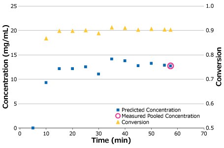
Figure 8.Process stability for pilot-scale run.
Discover our extensive range of Pellicon® filters, tailored to meet your unique process requirements. Visit our product page to learn more.
Related Products
如要继续阅读,请登录或创建帐户。
暂无帐户?