Energy Harvesting Using Lead Zirconium Titanate-Based Ceramic Nanowires
Introduction
Among various ceramics, one-dimensional (1-D) piezoelectric ceramics have attracted significant scientific attention for use in energy harvesting.1–3 One-dimensional piezoelectric nanostructures are the smallest dimensional structures capable of the efficient transport of electrons and, thus, have the potential to yield high energy conversion efficiency.4 Further, the high mechanical strength and flexibility of the 1-D nanostructures enable sensitivity to small, random mechanical disturbances that can be converted into electrical signals useful for both energy harvesting and nanoscale sensing.5–7 The sensitivity of 1-D piezoelectric nanostructures is highly dependent on the properties of the piezoelectric material. This makes the identification of materials with a high piezoelectric coupling coefficient important. One-dimensional piezoelectric nanostructures, such as nanowires (NWs) comprised of ZnO, BaTiO3, and NaNbO3 have been studied to achieve this goal.6,8–11 However, the relatively low piezoelectric coupling coefficient of these compositions restricts their applications. The highest measured piezoelectric coupling coefficient for ZnO nanowires is reported to be ~13 pm/V;8,9 for BaTiO3 nanowires, it is 50 pm/V.10,11
Lead zirconium titanate (PZT) is considered a promising piezoelectric material for sensor and transducer applications because it exhibits outstanding piezoelectric coupling at compositions near the morphotropic phase boundary (MPB) between the tetragonal and rhombohedral phases. It has been reported that the piezoelectricity of PZT can further be enhanced by doping and thermal processing.12–14 In particular, PZT NWs have attracted scientific interest due to their potential for providing excellent piezoelectric properties in a 1-D structure.
Numerous methods have been developed to produce PZT NWs, including hydrothermal,15–19 template-infiltration,20–22 electrophoresis,23 pulsed laser deposition (PLD),24 and electro-spinning.12,25 However, most of these methods suffer from low yield and cost concerns. In contrast, recent reports demonstrate that a two-step hydrothermal process can be used to achieve high efficiency 1-D PZT NWs with controllable composition, variable crystal size, and high yields.3
In this article, we report on our research into the structural and piezoelectric properties of hydrothermally synthesized perovskite PZT [Pb(ZrxTi1-x)O3] nanowires using the two-step approach with the Zr:Ti molar ratios of 0.52:0.48 and 0.2:0.8. The Zr:Ti molar ratios of 0.52:0.48 and 0.2:0.8 were deliberately chosen to emphasize the importance of MPB proximity on piezoelectric properties of Pb(ZrxTi1-x)O3. The ratio of 0.52:0.48 leads to PZT with composition near MPB, whereas the ratio of 0.2:0.8 keeps the Pb(ZrxTi1-x)O3 away from MPB. A refined piezoelectric force microscopy (PFM) testing method was applied to measure the coupling coefficient of the NWs. In addition, the PZT NWs were used in the fabrication and testing of an ambient mechanical vibrational energy harvester. The high piezoelectric coupling coefficient and high power density of the PZT NWs near the MPB demonstrates the potential to replace existing materials in sensing and energy harvesting applications.
Synthesis and Structural Properties
The synthesis of PZT [Pb(ZrxTi1-x)O3] NWs using a two-step hydrothermal process is summarized schematically in Figure 1A (experimental details regarding this can be found in reference 3). In the first step, H2ZrxTi1-xO3 NWs are synthesized hydrothermally using zirconium propoxide (70% in 1-propanol) (Prod. No. 333972) and titanium isoproxide as precursors (Prod. No. 377996). In the second step, the H2ZrxTi1-xO3 NWs serve as a template and are dispersed in a Pb(NO)3 solution under hydrothermal conditions to yield PZT NWs. The as-synthesized NWs crystallize in PbTiO3-type phase (designated as the PX phase). However, they adopt the perovskite phase after heat treatment at 600 °C for 30 min. The comparison of the scanning electron micrographs (SEM) of the H2ZrxTi1-xO3 nanowires obtained from the first step (Figures 1B and 1C), and those of the heat-treated Pb(ZrxTi1-x)O3 nanowires (Figures 1D and 1E), reveal that the 1-D shape of the NWs remains unaltered when the PX phase PZT nanowires adopt the perovskite phase. The XRD pattern of Pb(ZrxTi1-x)O3 nanowires is shown in Figure 1F. The diffraction peaks of the XRD pattern are clearly distinguishable and can be indexed to the perovskite PZT structure, which also confirms the complete conversion from H2ZrxTi1-xO2 to PZT nanowires in the second synthesis step. The successful conversion is further confirmed by the presence of Pb, Zr, and Ti peaks in energy dispersive X-ray spectroscopy (EDX) patterns (Figures 1G and 1H) of the PZT nanowires. The intensity of the Zr peak in the EDX pattern of Pb(Zr0.52Ti0.48)O3 nanowires is larger than that of Pb(Zr0.2Ti0.8)O3 NWs, which proves the higher Zr molar ratio in Pb(Zr0.52Ti0.48)O3 nanowires.
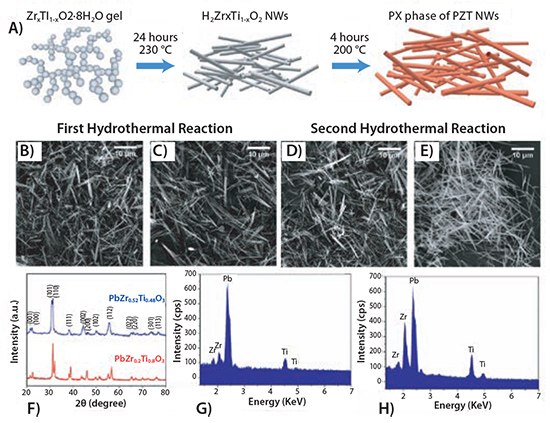
Figure 1. (A)Schematic of synthesis of PZT [Pb(ZrxTi1-x)O3] NWs using two step hydrothermal process; SEM images of (B) H2Zr0.2Ti0.8O2, (C) H2Zr0.52Ti0.48O2, (D) Pb(Zr0.2Ti0.8)O3, (E) Pb(Zr0.52Ti0.48)O3; NWs (F) XRD patterns of PZT NWs obtained after second hydrothermal step and heat treatment at 600 °C; EDX patterns of PZT [Pb(ZrxTi1-x)O3] NWs with (G) Zr:Ti=0.2:0.8 and (H) Zr:Ti= 0.52:0.48.
Piezoelectric Properties
Piezoelectric force microscopy (PFM) is a widely used technique to determine the piezoelectric properties and the application potential of piezoelectric nanowires. However, the accurate determination of the piezoelectric coupling coefficient using the PFM method severely suffers from a low signal-to-noise ratio.15,26 For example, measurement of the butterfly loop and phase change of PZT NWs as a function of the applied electric field by Wang et al. could not determine the piezoelectric coupling coefficient due to the poor signal-to-noise ratio.15 Xu et al. have reported that the electromechanical coupling of piezoelectric NWs can be quantitatively measured by using a built-in lock-in amplifier and a commercial PFM software package.26 However, the accuracy of the electromechanical coupling obtained from the use of commercial code is considered unreliable as it only provides a single number without allowing the direct analysis of the piezoelectric response. In order to measure the piezoelectric strain coupling coefficient of the PZT NWs quantitatively, refined PFM testing was performed using the experimental setup shown schematically in Figure 2A.15 The samples for the PFM were prepared by drop-casting the sonicated ethanol suspension of Pb(ZrxTi1-x)O3 NWs on a Pt/Ti-coated silicon wafer and drying in air. The accurate topography of the NWs (Figures 2B and 2C) was determined by performing a low scan speed (0.5 μM/s) atomic force microscopy (AFM) scan in non-contact mode. For measuring the electromechanical response, the conductive AFM tip was placed on the top facet of NWs with a force of 1,500 nN and switched to contact mode; then, triangular 1 Hz AC voltage of varying amplitudes was applied to the Pt/Ti layer on the silicon wafer. During the measurement, the AFM tip serves as the ground. The electromechanical displacement and phase response caused by the piezoelectric effect were collected 100 times; to minimize the errors associated with noise, these signals were filtered with a band pass filter centered at the waveform excitation frequency and averaged. The bipolar voltage dependence of the averaged displacement with a standard deviation of less than 30 pm from the unpoled PbZr0.2Ti0.8O3 and PbZr0.52Ti0.48O3 NWs are shown in Figures 2D and 2G, respectively. The butterfly-like appearance of the displacement loops is attributed to the nature of domain motion and the piezoelectric properties of the PZT nanowires. The hysteresis loop of phase versus voltage from the PbZr0.2Ti0.8O3 and PbZr0.52Ti0.48O3 NWs, with a standard deviation of less than 3 degrees, is shown in Figures 2E and 2H, respectively. Here, the phase change from 90° to –90° during the application of the excitation waveforms originates from switching the polarization direction of the nanowire with the coercive field matching in both the phase and amplitude loops. From Figure 2H, the coercive field of PbZr0.52Ti0.48O3 NWs of 200 nm diameter is estimated to be 50 kV/mm. The coercive field of PbZr0.52Ti0.48O3 NWs is larger than the bulk materials (2.5 kV/mm) and the increase is believed to originate from the small grain size of the nanowires and from grains that are not oriented along the electric field direction.27–29 The piezoelectric coupling coefficient (d33) of the PZT PbZr0.2Ti0.8O3 (40 ± 5 pm/V) and PbZr0.52Ti0.48O3 (80 ± 5 pm/V) NWs was determined from the displacement versus unipolar voltage loops shown in Figures 2F and 2I, respectively. We note that the d33 for PbZr0.52Ti0.48O3 is larger than that of PbZr0.2Ti0.8O3. This indicates that the enhanced electromechanical coupling of PbZr0.52Ti0.48O3 can be attributed to its proximity to the morphotropic phase boundary between the ferroelectric rhombohedral and tetragonal phases brought about by the higher concentration of Zr. The d33 value of PbZr0.52Ti0.48O3 NWs (80 pm/V) was found to be larger than that of prototype PZT NWs (50 pm/V) and ZnO nanowires (13 pm/V), which are widely used in energy harvesters.8,9,15
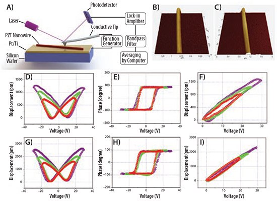
Figure 2. (A)Schematics of piezoelectric force microscopy (PFM) testing setup; (B) topography of PbZr0.2Ti0.8O3 and (C) PbZr0.52Ti0.48O3 NWs. Displacement of PZT nanowires when subjected to three bipolar excitation waveforms of varying amplitude for (D) PbZr0.2Ti0.8O3 and (G) PbZr0.52Ti0.48O3. Phase change of PZT nanowires when subjected to three bipolar excitation waveforms of varying amplitude: (E) PbZr0.2Ti0.8O3 and (H) PbZr0.52Ti0.48O3. Displacement of PZT nanowires when subjected to three unipolar excitation waveforms of varying amplitude: (F) PbZr0.2Ti0.8O3 and (I) PbZr0.52Ti0.48O3.
Energy Harvesting
The energy harvesting performance of the new PZT NWs was further demonstrated by fabricating a nanocomposite by combining PZT NWs with polydimethylsiloxane (PDMS). The PDMS is chosen as a matrix because it not only protects the NWs from the strain generated in the energy harvesting test, but due to its large elasticity and ability to hold over 100% of tensile strain without mechanical failure, it can also withstand large deformation.30,31 The mixture of PZT NWs and PDMS is first tape-casted on a Ti foil coated with Au (Ti thickness = 35 μm; Au coating = 20 nm) and then cured at 150 °C for 12 hr. The Ti foil serves as the bottom electrode in the device. To ensure the alignment of the PZT NWs dipoles in the direction of the electric field, which is normal to the face bottom Ti electrode, the cured mixture was poled at 150 °C for 2 hr with a custom corona poling setup at 15 kV. After this, a 200 nm thick silver leaf, which acts as the second electrode, is overlaid on the top of the nanocomposite.
Figures 3A and 3B show the schematic of the energy harvester and the cross-sectional view of the 50:50 wt % nanocomposite of PbZr0.52Ti0.48O3 NWs and PDMS, respectively. In the energy harvester, under stress induced by vibration, the PZT nanowires generate potential differences between the two electrodes and serve as an energy generation source. Figure 3B shows that the NWs are well distributed throughout the PDMS matrix. For the nanocomposite, the maximum weight percent of NWs was set to 50%, as higher concentrations might lead to poor dispersion of the NWs. In the energy harvester, the nanocomposite serves as a cantilever which can easily vibrate at the resonant frequency. The cantilever is formed by attaching the root of the nanocomposite beam to a glass substrate with epoxy (Figure 3A). In order to perform a power density comparison for all energy harvesters tested here, the dimensions of the nanocomposite was kept at ~2 cm (L) × 1 cm (W) × 0.018 cm (T).
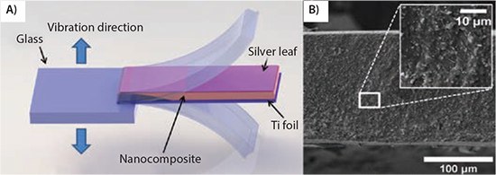
Figure 3. (A)Schematics of PZT/PDMS nanocomposite-based energy harvester. (B) A crosssection image of the 50:50 wt % PbZr0.52Ti0.48O3 NWs and PDMS nanocomposite.
To investigate the application potential of the PZT NWs and PDMS nanocomposite, the voltage and current generated from the nanocomposite was first screened by periodic manual bending and releasing. The periodic manual bending and releasing is the commonly adopted method used for primary screening of the application potential of nanocomposite-based energy harvesters. The open circuit voltage (Voc) was measured by a high impedance (1 TΩ) voltage follower where the short circuit current (Isc) was measured by a high speed electrometer. The Voc graph of the 50:50 wt % PbZr0.52Ti0.48O3 NWs PDMS nanocompositebased energy harvester is shown in Figure 4A. Under periodic bending and release, the device generates voltages ranging between 6 to 7 V, which is more than twice that of a NaNbO3 NWs nanocomposite (3.2 V) and 3 times larger than a ZnO NWs nanocomposite (2.03 V).32,33 The large peak value of Voc in present nanocomposites can be attributed to the enhanced piezoelectric coefficient of PbZr0.52Ti0.48O3 NWs. However, it should be emphasized that merely a comparison of peak Voc does not fully demonstrate the advancement of PZT/PDMS nanocomposites since it also highly depends on strain rate. Therefore, a controlled excitation is a must to quantify the actual performance. Figure 4C shows the magnified Voc graph. Associated with bending strain, the Voc shows a negative peak, which is followed by a large positive peak corresponding to the release of the bent nanocomposite, resulting in a large strain rate. The Isc output graph from the energy harvester device is shown in Figure 4B. The periodic bending and release continuously generates a current ranging between 100 to 120 nA. The oscillation of the Voc and Isc observed in Figures 4C and 4D, respectively, is attributed to the damping effect of the cantilever, and it further confirms that the output signals were, indeed, generated by the PZT/PDMS nanocomposite.
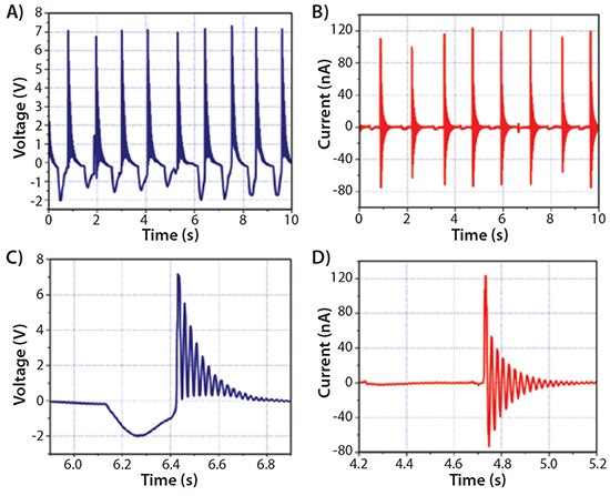
Figure 4.Signal generation from the 50:50 wt % PbZr0.52Ti0.48O3 NWs and PDMS nanocompositebased energy harvester. (A) Open circuit voltage and (B) short circuit current generation from periodic, manual bending and releasing of the cantilevered sample with magnified views of the (C) voltage output and (D) current output.
Typically, ambient vibrational energy exists in the 1 Hz to 1 kHz range.34,35 Thus, the performance of the PZT/PDMS nanocomposite energy harvester was tested for ambient mechanical vibrations, and a dynamic characterization using frequency response function (FRF) was performed.3 For the nanocomposite cantilever, the FRF reveals a resonant frequency of 43 Hz.
In order to demonstrate the potential for high-performance nanocomposite energy harvesting with PZT nanowires at relatively low frequencies, the alternating current (AC) power and power density were calculated with respect to varying load resistors. The AC power (PL) was determined by measuring the root mean square (RMS) voltage (VL) across external resistive load (RL, ranging from 1 MΩ to 500 MΩ ) at the resonant frequency using Equation 1:36

Figures 5A and 5B show the AC power and power density, respectively, from the 50:50 wt % PbZr0.52Ti0.48O3 NWs PDMS energy harvester. For an RL below 30 MΩ, the power increases rapidly and peaks at a value of 88 nW for RL = 40 MΩ.34,37 For RL >40 MΩ, the power continues to reduce since VL starts saturating toward the Voc. Figures 5C and 5D show concentration dependence of VPP and power density of PZT NWs/PDMS nanocomposites. For both PbZr0.52Ti0.48O3 and PbZr0.2Ti0.8O3 nanocomposites, the VPP and power density increase with increasing concentration. The maximum power density for 50:50 wt % PZT NWs and PDMS harvesters with PbZr0.52Ti0.48O3 and PbZr0.2Ti0.8O3 was estimated to be 2.4 and 0.75 μW/cm3, respectively (Figure 5D). The higher power density value (~3 times) for the PbZr0.52Ti0.48O3-based nanocomposite compared to PbZr0.2Ti0.8O3 is attributed to the enhanced piezoelectric properties of PbZr0.52Ti0.48O3 brought about by the proximity of the material to MPB.

Figure 5.Power characterization of PZT/PDMS nanocomposite-based energy harvesters. (A) AC power and (B) power density of the PbZr0.52Ti0.48O3/PDMS nanocomposite energy harvester with varying load resistors (RL) showing a peak power of 88 nW and a peak power density of 2.4 μW/cm3 at an optimal RL of 40 MΩ. This peak power level increases with increasing weight percent of PbZr0.52Ti0.48O3 nanowires. (C) VPP, IPP and (D) peak power density of PZT/PDMS nanocomposite energy harvester is increased by increasing PZT nanowires weight percent.
Conclusions
The importance of the morphotropic phase boundary (MPB) on the piezoelectric properties has been demonstrated. A high power density (2.4 μW/cm3) for the PbZr0.52Ti0.48O3 NWs/PDMS nanocomposite-based energy harvester was obtained at a relatively low frequency. This power density is comparable to several cantilever-based energy harvesters stimulated by base vibration38–40 and demonstrates the application potential of PZT NWs in energy harvesting and sensing. Furthermore, by using the two-step hydrothermal process, these PZT NWs with tunable composition can be synthesized at high yield, increasing their importance in energy harvesting and sensing applications.
Acknowledgment
The authors gratefully acknowledge support from the Air Force Office of Scientific Research under contract FA9550-12-1-0132.
Product Highlight
Make Your Own Lithium-ion Batteries
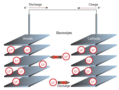
Applications of lithium-ion batteries (LIBs) extend from modern electronics to automobiles. Order ready-to-use electrolyte solutions and electrode sheets in battery grade to fabricate your LIB.
For a complete list of LIB materials, including electrode powders, electrolytes, solvents and additives, visit our Lithium-ion Batteries page.
Materials
References
如要继续阅读,请登录或创建帐户。
暂无帐户?