High-Energy Lithium-Ion Batteries
- Introduction
- Challenges and Opportunities for Nickel-rich Layered Oxide Cathode Materials
- Production Processes for Nickel-Rich Layered Oxide Cathode Materials
- Production Detail for Nickel-Rich Layered Oxide Cathode Materials
- Cathode Material Synthesis via a Continuous Couette–Taylor Flow Reactor
- Summary
Introduction
Lithium ion batteries (LIBs) are the state-of-the-art rechargeable electrochemical power source that currently dominates high energy density applications such as portable electronic devices and electromobility.1–3 To enable faster and more extensive market penetration of electric vehicles (EVs), the industry must achieve driving ranges of at least 500 km at an affordable cost. However, achieving such a feat requires further innovation to improve efficiency by increasing energy density (>500 Wh L-1) and reducing cost (<125 US$ kWh-1) at the battery pack level.2 Despite further possible optimizations of the LIB cell and pack design (e.g., cell design and housing, cooling system), the development of advanced LIB cell chemistries will have a significant impact on energy content and cost savings.2,4,5
Challenges and Opportunities for Nickel-rich Layered Oxide Cathode Materials
Over the last decade, the establishment of state-of-the-art positive electrode (cathode) materials in high-energy LIB cells has come as a result of advancements in nickel (Ni)-containing LiMO2-type layered oxides (where M denotes metals such as Ni, Co, Mn, Al, etc).2,5,6 In particular, these polyatomic compounds appear as variations of Li[NixCoyMnz]O2 (x+y+z = 1; NCMxyz) and Li[Ni1-x-yCoxAly]O2 (NCA).
Two major strategies are currently employed to increase the energy content of advanced cathodes to target values of ≥800 Wh kg-1 and ≥4,000 Wh L-1. The first approach is to increase the Ni-content of the layered oxides (≥80%) to enhance specific cathode capacity; the second strategy is to increase the charging cut-off potential (e.g., >4.3 V vs. Li|Li+) of lower Ni (≤60%) cathode formulations.5,7 Lately, LIB cells based on NCM811 (e.g., pouch format cells by CATL Battery) and NCA chemistries (21700 cylindrical format cells by Panasonic), having Ni-contents of ~≥80% and exhibiting 80–100 g Co per kWh and <50 g Co per kWh, respectively, have already entered the EV market.5 Besides energy density improvements, a major driving force for further cathode material development is to lower the cobalt (Co) content of the cathode, a scarce and costly element. Cobalt mining primarily occurs in politically unstable regions in Central Africa, involving severe environmental pollution as well as widespread allegations of extraction by child labor.2,5 For this reason, the scientific community has invested heavily in research to develop Co-free or low-Co Ni-rich, layered oxide cathode materials.8,9
However, both of the previously mentioned strategies result in severe challenges concerning the cathodes’ cycle life and thermal stability (safety). These two features often present hurdles due to the limited structural stability upon excessive de-lithiation, involving multiple phase transformations of both bulk (i.e., lithium ordering) and particle surface (i.e., layered to rock salt formation), especially for Ni-rich cathode compositions.5 Further challenges include parasitic side reactions, such as electrolyte oxidation accompanied by gas evolution, transition metal dissolution and cross-talk phenomena, and as well as particle (micro)-cracking by anisotropic lattice distortion.5,7,10,11
Besides chemistry, the electrochemical performance of cathode materials also depends on their particle properties, such as morphology and microstructure (size and shape of primary particles and their alignment within the secondary particle), size distribution, tap density, specific surface area, and surface characteristics.5 Thus, tailored particle engineering of layered cathode materials during synthesis allows for an achievable optimum energy output while still addressing cycle life and thermal stability aspects via particle refinement strategies.
Production Processes for Nickel-Rich Layered Oxide Cathode Materials
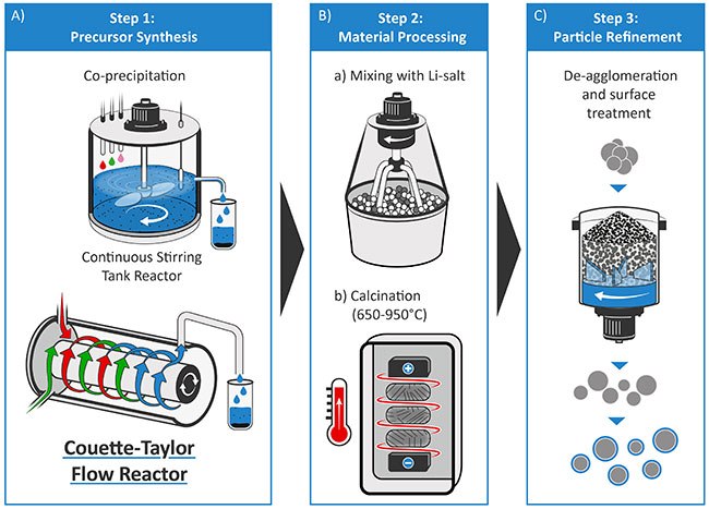
Figure 1 illustrates the three critical steps of the production process of LiMO2-type layered oxide cathode materials, (A) precursor synthesis, (B) material processing, which includes precursor lithiation and calcination, and (C) particle refinement.2,5 The precursor materials are typically prepared via an aqueous co-precipitation route in a batch reactor, in a continuously stirred tank reactor (CSTR), or a Couette–Taylor- Flow-Reactor (CTFR), which are introduced later in this work.12,13

Figure 1.Schematic illustration of the production process for layered oxide cathode materials for LIB cells. A) Step 1: Precursor synthesis via coprecipitation in a CSTR or CTFR, followed by post-particle treatments (filtration, washing, drying, sieving). B) Step 2: Lithiation via mixing with a lithium salt (LiOH or Li2COLi3) and calcination (650–950 °C). C) Step 3: Particle refinement procedures by de-agglomeration of particles and surface treatment (like post-calcination, etc.).
The careful adjustment of each production step and multiple synthesis parameters is required to obtain the required cathode particles with tailored characteristics. Various studies have suggested that precursors significantly affect the properties of cathode materials through their chemical composition, particle morphology, and size distribution.5,12,14 Therefore, systematic studies in terms of optimum synthesis parameters for co‑precipitation are mandatory, e.g., by adjusting the pH value, amount of ammonia concentration, and the type of base (hydroxide vs. carbonate). Furthermore, the lithiation/calcination process requires optimization concerning its conditions (e.g., LiOH vs. Li2CO3, calcination temperature, air vs. O2 atmosphere), while the post-treatment for Ni-rich materials typically necessitates a high corrosion resistance of the used equipment as well as a strict humidity control.5
It is well known that the particle properties of the NCM precursor materials strongly depend on the crystal agglomeration mechanism. This feature occurs via consecutive steps of physical adhesion of the crystals forming aggregates, followed by aggregate growth.15 The agglomeration process is complex and depends on various synthesis conditions. These conditions include the type and layout of the reactor, determining the fluid motion (e.g., turbulent vs. laminar) and, thus, the particle collisions resulting in agglomeration.15 Two types of chemical reactors, batch reactors, and CSTRs are widely adopted for precursor material preparation.13 A third reactor, the CTFR — also known as Taylor vortex reactor (TVR), is currently being reviewed to provide improved mixing of the reactants (Figure 1A).13,15–19 The co-precipitation route within batch or CSTR processes are commercially applied for the NCM precursor production, due to its advantages for achieving particles having a homogeneous composition, narrow size distribution and high tap density.12,20 However, these two production routes also suffer from shortcomings, such as typically long reaction times (~15–25 h), process complexity for CSTR operation as well as possible batch-to-batch variability and labor-intensive operation for batch processes.13 In this respect, process development and scale-up of cathode material synthesis towards larger batch sizes (≥1 kg; e.g., by continuous processes) are a critical bridge between fundamental laboratory research, prototype development for validation, and high-volume production.20
Production Detail for Nickel-Rich Layered Oxide Cathode Materials
To prepare an NCM811 precursor (Ni0.8Co0.1Mn0.1(OH)2) as in the first step of Figure 1A, feed 1.5 molar aqueous solutions of the divalent transition metal salts, nickel sulfate hexahydrate (NiSO4∙6H2O, 227676), cobalt sulfate heptahydrate (CoSO4∙7H2O, C6768), and manganese sulfate monohydrate (MnSO4∙H2O, M7634) into the reactor. Simultaneously a 3.0 molar aqueous base solution of sodium hydroxide (NaOH, 567530) and chelating agent of ammonium hydroxide (12 wt.% NH4OH, 338818) is pumped into the reactor under pH (~12) and temperature control (~60 °C), causing the metal hydroxide (M(OH)2) precursor precipitates.
Afterward, the obtained precursor requires filtration and repeated washing to remove impurities (i.e., sodium and sulfate ions), followed by drying and (optional) sieving to adjust to a particular particle size distribution. In the second step (Figure 1B), mix the precursor particles with a stoichiometric amount of a lithium-containing salt, i.e., lithium hydroxide monohydrate (LiOH·H2O, 402974) or lithium carbonate (Li2CO3, 601470), and calcine in a temperature range between ~650–950 °C in oxygen atmosphere.2,5 Even though Li2CO3 has a lower cost, Ni-rich cathodes are known to have more favorable particle and electrochemical characteristics when calcined with LiOH.2,5 The final step (Figure 1C) requires particle refinement approaches, such as de-agglomeration, purification, drying and sieving, as well as surface treatments, e.g., post-calcination, to stabilize the cathode material interface.2,5
Cathode Material Synthesis via a Continuous Couette–Taylor Flow Reactor
For electric vehicle (EV) applications, the volumetric energy density (Wh L-1) of battery materials and the resulting cells are broadly seen as more important than specific energy (Wh kg-1). Consequently, the cell requires fabrication of composite electrodes with high areal capacities >3–4 mAh cm-2 and pressed electrode densities of 3.0–3.4 g cm-3.5 Scientists can achieve a high electrode density by using cathode materials with high crystallographic density (>4 g cm-3), large particle size (≥10 μm), and bimodal size distribution; however, a spherical particle morphology reduces slurry viscosity and improves packing density.5,21 The CTFR has recently emerged as a popular reactor type for the continuous production of cathode precursors.13,15,17–19 The CTFR conveys numerous advantages over established CSTR and batch processes, such as allowing very homogeneous micro-mixing with higher mixing intensity, shorter processing times, design of dense particles by fast reaction kinetics, and design of highly uniform spherical particles with narrow size distribution.
Figure 2 shows the setup and operating principle of a CTFR (LCTR®-Tera 3300, Laminar). The reaction tube of the CTFR consists of two coaxially arranged cylinders with a narrow reaction zone (6.55 mm) in between, as illustrated in Figure 2A. Upon operation, the inner cylinder rotates, inducing a stable Taylor-vortex flow pattern above a threshold rotational speed. The confined Taylor vortices increase the shear forces in the reaction mixture, promoting the agglomeration of spherical precipitates with a narrow particle size distribution (Figure 2B).15,18,19,22

Figure 2.Schematic illustration of A) the experimental setup for coprecipitation of metal hydroxides in a continuous CTFR and B) Taylor vortex flow patterns induced along the reaction tube of the CTFR. Adapted with permission from references 15 and 18, 2011 Elsevier and 2015 ACS Publications (respectively).
The Taylor-vortex flow patterns form above the critical Taylor number (Ta), as shown in equation (1), in which d is the gap of the cylinders, ri is the radius of the inner cylinder, ωi is the rotational angular speed, and ν is the viscosity of the fluid.15-16,23

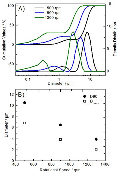
Obtaining precursor materials with optimized particle characteristics requires scientists’ careful evaluation and selection of various CTFR parameters. Adjustable parameters for the co-precipitation process include synthesis temperature (T), mean residence time (τ), pH value, concentrations of the reactant solutions, as well as the rotational speed (ωi) of the inner cylinder. For the production of hydroxide precursors (Ni0.8Co0.1Mn0.1(OH)2), the operation temperature was set to ~60 °C and the pH value was adjusted to ~12. Figure 3 and Figure 4 show the impact of varying rotational speeds (500, 900, and 1300 rpm; τ : 4 h) on the resulting particle morphology and particle size distribution.

Figure 3.SEM images of Ni0.8Co0.1Mn0.1(OH)02 precursor materials synthesized via the CTFR (pH value: 12; T: 60 °C; τ: 4 h) showing the dependence of the rotational speed (ωi) of the inner cylinder. A) ωi: 500 rpm; B) ωi: 900 rpm; C) ωi: 1300 rpm.

Figure 4.Particle size distribution of Ni0.8Co0.1Mn0.1(OH)2 precursor materials synthesized via the CTFR (pH value: 12; T: 60 °C; τ: 4 h; ωi: 500-1300 rpm). A) Cumulative values and density distribution; B) Average values of D90 and mean particle size distributions.
One can observe that the obtained NCM811 precursor materials display a bimodal particle size with a narrow size distribution (Figure 4A). Additionally, the rotational speed significantly influences the particle size, which increases with decreasing ωi, as depicted by the average D90 and Dmean values (Figure 4B). The tap density of the precursor materials (~1.6 g cm-3) is nearly independent of the changes in particle size. Furthermore, one can recognize the more uniform spherical particles obtained at moderate or low rotational speeds (≤900 rpm, Figure 3).
In the next step of cathode material production, scientists lithiated the precursor materials by mixing them with LiOH·H2O and subsequent calcination (800 °C, 10 h, O2 atmosphere). In an exemplary result, Figure 5 displays the comparison of the particle morphology for an NCM precursor particle (Figure 5A) and a lithiated NCM811 particle (Figure 5B). One can see that the nanosized primary particles of the precursor become larger primary particles for NCM811 during the calcination step at 800 °C (Figure 5B). The tap density for the NCM811 materials ranges from ~1.5–2.0 g cm-3, depending on the rotational speed (500–1300 rpm). Furthermore, one can observe a change of the BET specific surface area (~0.6–1.5 m2 g-1), which correlates well with the changes in the particle size distribution, i.e., a decrease of the average particle size results in an increase of the specific surface area.

Figure 5.SEM images of the A) precursor material Ni0.8Co0.1Mn0.1(OH)2 synthesized via the CTFR (pH value: 12; T: 60 °C; τ: 2 h; ωi: 500 rpm) and B) the lithiated Ni0.8Co0.1Mn0.1O2 material obtained via lithiation using LiOH (calcination at 800 °C for 10 h, O2 atmosphere).
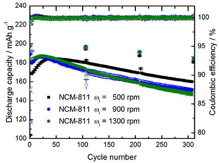
Figure 6 presents the long-term charge/discharge cycling performance of NCM811 || graphite LIB full-cells for three different NCM811 materials, i.e., for precursor materials obtained at different rotational speeds (pH value: 12; T: 60 °C; τ: 2 h; ωi: 500, 900 and 1300 rpm). From the figure, it can be observed that the particle characteristics have a significant impact on the electrochemical performance of the full-cells. For instance, the larger NCM811 particles (ωi: 500 rpm) display a lower 1st-cycle Coulombic efficiency and lower initial capacity but higher capacity retention. In contrast, the smaller particles (ωi: 900 and 1300 rpm) exhibit a higher 1st cycle Coulombic efficiency and higher initial capacity, while the capacity retention is inferior compared to larger particles. Future systematic studies in terms of material design and electrochemical performance analysis are mandatory to validate structure-performance correlations.

Figure 6.Charge/discharge cycling performance of NCM811||graphite full-cells (two-electrode setup; CR2032 coin cells). Cycling conditions: Cell voltage range of 2.8-4.3 V; 3 formation cycles at 0.1C, followed by cycling at 0.5C (1C=200 mA g-1) with 0.1C cycling steps after each 100 cycles. Positive electrode: NCM811:PVdF binder:Super C65 = 92:4:4; areal capacity: 2.0 mAh cm-2; graphite negative electrode: 2.6 mAh cm-2; Electrolyte: 1M LiPF6 in ethylene carbonate (EC)/diethyl carbonate (DEC) (3:7 by weight).
Summary
The cathode is the decisive cell material for further increasing energy content and lowering the costs of future advanced LIB cells; cathode chemistry and morphology both contribute equally to achieving these goals. The CTFR is a powerful reactor type for the continuous co-precipitation of spherical precursors for Ni-rich layered cathode materials, enabling the synthesis of highly uniform particles under relatively short residence times. Scientists can adjust particle characteristics such as particle morphology and size distribution, by choosing suitable synthesis parameters including temperature, residence time, and rotational speed. In this work, the authors of this paper presented the successful synthesis of NCM811 cathode materials and their electrochemical characterization in LIB full-cells. They demonstrated promising performance that can be further improved by systematic adjustment of synthesis conditions for an optimum particle design.
Acknowledgments
The authors wish to thank the German Federal Ministry for Economic Affairs and Energy (BMWi) for funding this work in the project “Go3” (03ETE002D). We also thank Andre Bar for graphical support.
Materials
References
To continue reading please sign in or create an account.
Don't Have An Account?