How to Make and Use Percoll Gradients
Section Overview
- Making and Diluting a Stock Solution of Percoll
- Diluting Stock Solutions of Percoll to Lower Densities
- The One-step Procedure for Diluting Percoll
- Diluting Percoll to a Desired Osmolality
- Effects of Osmolality on Apparent Buoyant Density of Cells and Subcellular Particles
- Factors Affecting Gradient Formation and Shape
- Discontinuous (Step) Gradients
- Continuous Linear and Non-linear Gradients
- Preformed Self-generated Gradients
- Gradients Formed in situ
- Maximum Sample Loading for Percoll Gradients
- A Model Experiment to Standardize Conditions for Percoll Gradients
Making and diluting a stock solution of Percoll
To use Percoll to prepare a gradient the osmolality of Percoll (undiluted) must first be adjusted with saline or cell culture medium to make Percoll isotonic with physiological salt solutions. Adding 9 parts (v/v) of Percoll to 1 part (v/v) of 1.5 M NaCl or 10X concentrated cell culture medium is a simple way of preparing a stock isotonic Percoll (SIP) solution. Final adjustment to the required osmolality can be accomplished by adding salts or distilled water. Because cell density depends on osmolality (Figure 6), the osmolality of the stock solution should be checked routinely with an osmometer to ensure reproducibility between experiments. For subcellular particles that aggregate in the presence of salts, the stock isotonic Percoll (SIP) can be made by adding 9 parts (v/v) of Percoll to 1 part (v/v) of 2.5 M sucrose.
The density of the SIP solution can be calculated from the following formula:

Where:
Vx = volume of diluting medium (mL)
Vo = volume of undiluted Percoll (mL)
ρo = density of Percoll (1.130 + 0.005 g/mL*)
ρ10 = density of 1.5 M NaCl = 1.058 g/mL (minor differences for other salts)
density of 2.5 M sucrose = 1.316 g/mL (minor differences for other additives)
ρi = density of SIP solution produced (g/mL)
Thus, for SIP in saline, ri = 1.123 g/mL and for SIP in sucrose, ri = 1.149 g/mL, assuming ro = 1.130 g/mL.
*Exact density as stated on the certificate of analysis.
Diluting stock solutions of Percoll to lower densities
Solutions of stock isotonic Percoll (SIP) are diluted to lower densities simply by adding 0.15 M NaCl (or normal strength cell culture medium) for cell work, or with 0.25 M sucrose when working with subcellular particles or viruses.
The following formula can be used to calculate the volumes required to obtain a solution of the desired density.
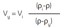
Where:
Vy = volume of diluting medium in mL
Vi = volume of SIP in mL
ρi = density of SIP in g/mL
ρy = density of diluting medium in g/mL
(density of 0.15 M NaCl is ~1.0046 g/mL) *
(density of 0.25 M sucrose is ~1.032 g/mL)*
ρ = density of diluted solution produced in g/mL
Example: To dilute 55 mL of SIP to a final density of 1.07 g/mL, determine the amount of 0.15 M NaCl required.

The above formula is useful for achieving densities that will be very close to the actual density desired. However, slight variations in volumes and densities of diluting media will affect final density. For determining actual densities, we recommend measuring the final density of Percoll solutions using a densitometer or refractometer.
Note: The graph in Figure 5 can also be used as an empirical guide to the density of solutions produced by diluting SIP with 0.15 M saline or 0.25 M sucrose. This graph refers to the dilution of SIP where SIP is 90% (v/v) undiluted Percoll osmotically adjusted by addition of 10% (v/v) saline or sucrose. To avoid confusion, it is therefore preferable to refer to the actual density of the working solution (or to state % SIP) rather than to refer to the solution as a percentage of Percoll in iso-osmotic saline or sucrose. This is particularly important when using the one-step dilution procedure described below, where a working solution of known density is obtained by diluting Percoll (undiluted) plus concentrated salts or sucrose to a final volume with distilled water.
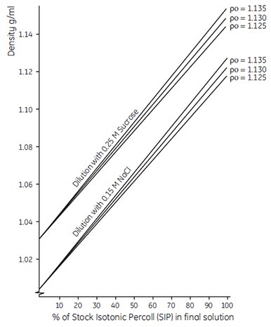
Figure 5.Dilution of Stock Isotonic Percoll (SIP) with isoosmotic saline or sucrose solution. Po is the density of the Percoll (undiluted). SIP is prepared as described. The calibration lines shown are for guidance only. For accurate density measurements, refer to the formula given in the text.
The one-step procedure for diluting Percoll
Percoll (undiluted) may be diluted directly to make a final working solution of known density by the following procedure. In a measuring cylinder, add 1.5 M NaCl or 2.5 M sucrose to 1/10 of the final desired volume (e.g. 10 mL for 100 mL of working solution). To this, add the required volume of Percoll (undiluted), calculated using the formula shown below. Make up to the final volume with distilled water.

Where:
Vo = volume of Percoll (undiluted) (mL)
V = volume of the final working solution (mL)
ρ = desired density of the final solution (g/mL)
ρo = density of Percoll (undiluted) (g/mL)
(Certificate of Analysis for exact density)
ρ10 = density of 1.5 M NaCl = 1.058 (g/mL)
(minor differences for other salts)
density of 2.5 M sucrose = 1.316 (g/mL)
(minor differences for other additions)
Example: To prepare 100 mL of working solution of Percoll of density 1.07 g/mL in 0.15 M NaCl. To 10 mL of 1.5 M NaCl, add

The above formula is useful for achieving densities that will be close to the actual density desired. However, slight variations in volumes and densities of diluting media will affect final density. For determining highly accurate densities, we recommend measuring the final density of Percoll solutions using a densitometer or refractometer.
Graphs similar to the one shown in Figure 5 can be drawn to relate the volume of Percoll (undiluted) to the final density.
Diluting Percoll to a desired osmolality
To make isotonic Percoll for most mammalian cells, it is common to dilute 9 parts of Percoll (undiluted) with 1 part of 1.5 M NaCl or 2.5 M sucrose solution. This Stock Isotonic Percoll (SIP) is then further diluted with physiological buffers according to needs. However, while this procedure has proved successful, it is rather simplistic and does not take into account the effect of having solid silica particles present (i.e. that 100 mL of Percoll stock contains a certain volume of solid silica, making the total aqueous volume less than 100 mL). Due to the volume occupied by silica, the electrolytes in the stock solution have a higher effective concentration than in physiological salt solution, and SIP made in this way will be hyperosmolal. Thus, determining the actual osmolality of the SIP has always been recommended.
Vincent and Nadeau (555) discuss the problem elegantly and described an equation which can be used to calculate the number of parts of Percoll which should be added to one part of 10× concentrated physiological salt buffer to obtain a SIP of any desired osmolality. The authors determined the fraction of the total volume of a Percoll stock solution which is occupied by silica and thus determined the ratio of volume of aqueous solution to that of total Percoll stock solution.

Where:
Vp = number of parts of Percoll to be added
Vc = number of parts of solute concentrate (e.g. 1.5 M NaCl) to be added
Oc = osmolality of solute concentrate (e.g. 1.5 M NaCl = 2880 mOsm)
Of = desired osmolality
R = ratio of aqueous volume to total volume of Percoll (typically = 0.85 for NaCl and 0.80 for sucrose)
Op = osmolality of Percoll undiluted (Certificate of Analysis)
The key variable in this equation is R, which is a measure of the real aqueous volume of a Percoll solution. The value of R is a function of the hydrodynamic volume occupied by the Percoll particles. This, in turn is a function of the ionic strength of the medium; that is, as ionic strength increases, hydrodynamic volume decreases. Thus, there is a difference in the R value of 1.5 M NaCl and 2.5 M sucrose.
To obtain a SIP of osmolality = 320 mOsm/kg H2O adjusted with 1.5 M NaCl (i.e., 10× concentrated physiological saline):

assuming:
2880 = osmolality of 1.5 M NaCl
(10× concentrated physiological saline)
20 = osmolality of Percoll undiluted
Therefore to obtain a SIP of 320 mOsm/kg H2O, one would add 10 parts Percoll to 1 part 1.5 M NaCl.
Effects of osmolality on apparent buoyant density of cells and subcellular particles
The very low osmolality of Percoll has facilitated the study of the interrelation of the separation medium osmolality with the apparent buoyant density of particles. Figure 6 shows the effects of banding rat liver hepatocytes in Percoll gradients having osmolalities of 200, 300 and 400 mOsm/kg H2O. The apparent buoyant density of the cells increases with increasing osmolality, due to removal of water from the cells. The same effect has been observed with mitochondria (Figure 7) and with lysosomes (Table 1). Even small changes in osmolality cause a large change in the apparent buoyant densities of these organelles. The actual recorded buoyant densities of particles banded in Percoll gradients at physiological osmolality are therefore much more likely to correspond to those existing in vivo, than when the particles are banded in sucrose or other centrifugation media.
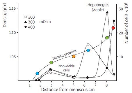
Figure 6.Fractionation of rat liver hepatocytes cells (35 × 106 cells in a volume of 2 mL) on a self-generated Percoll gradient (8 mL solution with a density of 1.065 g/mL). The osmolality of the Percoll solution was varied by adding NaCl to 200 mOsm, 300 mOsm and 400 mOsm. Centrifugation was performed in a Beckman rotor 30.2 for 15 min at 35 000 × g at a temperature of 4 °C. Density gradient determined using Density Marker Beads (page 23) (27, reproduced by kind permission of the authors and publisher).
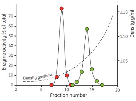
Figure 7. The density distribution of mitochondria from rat liver cells after incubation in iso-osmotic buffer (red) and buffer containing 17.5% albumin (green). Centrifugations were performed in a Beckman 65 rotor (23° angle) for 30 min at 40 000 × g (59, reproduced by kind permission of the authors and publisher).
A lysosomal fraction from rat hepatocytes was recovered from a Percoll/0.25 M sucrose gradient at a density of 1.0 to 1.05 g/mL and incubated in the media described in the table for 1 h at 37 °C. The buoyant density was then redetermined in a gradient of Percoll/0.25 M sucrose (27, reproduced by kind permission of the authors and publisher).
Factors affecting gradient formation and shape
Although the hydrated volume of Percoll particles is smaller in the presence of 0.15 M NaCl than in Percoll/0.25 M sucrose, the sedimentation rate of the particles is faster due to the lower viscosity of Percoll in saline. Thus, when Percoll is made iso-osmotic with a final concentration of 0.15 M saline or a tissue culture medium of equivalent ionic strength, it will form a self-generated gradient about 2 to 3 times faster than the equivalent Percoll solution made iso-osmotic with a final concentration of 0.25 M sucrose.
Centrifugation and time are interrelated in that it is the total (g force) × (time) which determines the shape of the gradient. A minimum of approximately 10 000 × g should be used for Percoll in 0.15 M saline and about 25 000 × g for Percoll in 0.25 M sucrose to self-generate gradients in anglehead rotors. Rotor geometry has a marked effect on gradient shape under given conditions as shown in Figure 8. As the angle approaches vertical, the pathlength for formation of the gradient becomes shorter and the gradient forms more rapidly. Figures 9 and 10 demonstrate that the initial concentration of Percoll also has some effect on the shape of the gradient formed.
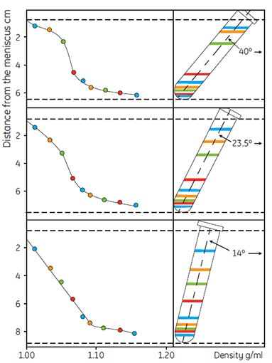
Figure 8.The effect of rotor angle on gradient development using Percoll. Starting density was 1.065 g/mL in 0.15 M NaCl. Running conditions: 30 000 × g for 14 min. Colored lines refer to the positions of the colored Density Marker Beads (45, reproduced by kind permission of the authors and the publisher).
Centrifugation in vertical rotors will form gradients of Percoll very rapidly. Care must be taken, however, to ensure that the compacted pellet of Percoll which may be formed under high speed centrifugation conditions does not contaminate the gradient during fractionation.
The use of swinging bucket rotors for self-generation of gradients is not recommended, due to the long path length and unequal g-force along the tube. However Jenkins et al. (personal communication and ref. 87) report some advantages in using these types of rotors for subcellular fractionation of liver organelles.
Zonal rotors can be used to form gradients of Percoll in situ. Gradients formed in zonal rotors have the same characteristics as those generated in angle-head rotors. Because of their large sample volumes, it is recommended that the separation conditions in a nonzonal rotor be empirically determined prior to scale-up in a zonal rotor. Zonal rotors have been used in the large scale purification of viruses (21) and for subfractionation of lysosomes (24).
When starting work with self-generated gradients, it is advisable to conduct a model experiment with colored Density Marker Beads (page 22) to produce a series of standard curves under known conditions which are characteristic of the angle-head rotor to be used for subsequent experiments.
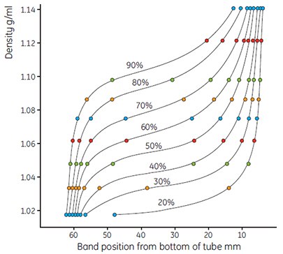
Figure 9.Use of colored Density Marker Beads to show gradient shape. Gradients formed from solutions of Percoll varying from 90% to 20% of stock isotonic Percoll in 0.15 M NaCl. Running conditions 23° angle-head rotor 30 000 × g, 15 min.
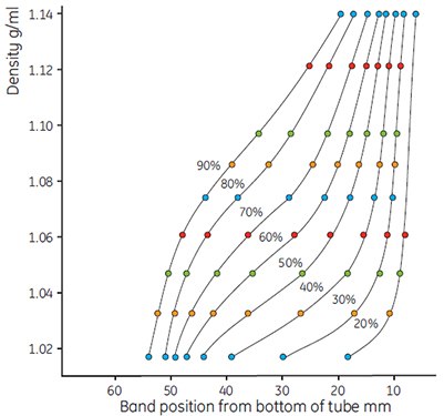
Figure 10.Use of colored Density Marker Beads to show gradient shapes. Dilutions of Percoll as in Figure 9, running conditions: 23° angle-head rotor, 60 000 × g, 15 min. Steeper gradients were formed by the greater g-force.
Discontinuous (step) gradients
Discontinuous gradients offer great flexibility and ease of use. Often, only a cushion of Percoll or a single step is all that is required to achieve excellent enrichment or resolution of a target cell type. For example, most blood cells can be enriched using discontinuous gradients (Figure 11).
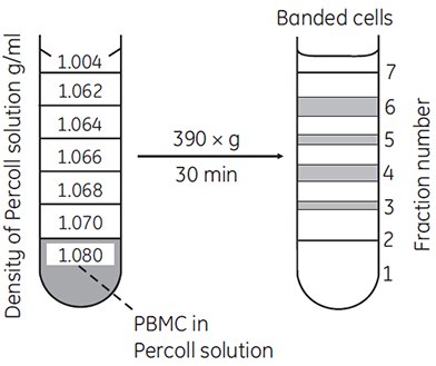
Figure 11.Separation of lymphocytes and monocytes by discontinuous density centrifugation in Percoll. 1.5 to 2.0 × 10⁷ PBMC (peripheral blood mononuclear cells) isolated on Ficoll-Paque™ were mixed in 11.25 mL of Percoll in Hanks BSS containing 1% HEPES buffer (density = 1.080 g/mL) and underlayered below the steps shown in the figure (69, reproduced by kind permission of the authors and publisher).
To form a discontinuous gradient, SIP is diluted to a series of different densities as described on page 12. The solutions of different density are then carefully layered in order of density one on top of another, starting with the most dense at the bottom of the tube. This is most conveniently done using a pipette or a syringe fitted with a wide-bore needle. It is important to keep the tip of the instrument against the wall of the tube just above the surface of the liquid to avoid a ”splash” and mixing at the interface. Formation of a sharp band of cells at a interface will occur only if there is a sharp change in density.
Centrifugation is performed using relatively gentle condition, such as 400 × g for 15 to 20 min in a bench-top centrifuge. These gentle conditions result in the isopycnic banding of cells at the relevant interfaces. The low-g conditions and short run time will not cause sedimentation of the Percoll and will not affect the gradient in any way.
Continuous linear and non-linear gradients
Continuous gradients are characterized by a smooth change in density from the top to the bottom of the tube. Instead of the obvious interfaces present in the discontinuous gradient, a continuous gradient can be thought of as having an infinitive number of interfaces. Therefore, isopycnic banding of cells occurs at the precise density of the cell.
To form such a gradient, SIP is first diluted to produce two solutions of known density at the limits of the range required, and then mixed using a dual-chamber gradient maker. A linear gradient spanning the range between the limits of the two starting solutions is formed.
A single-channel peristaltic pump in combination with a gradient mixer can be used to generate linear, convex, and concave gradients, depending upon the relative diameters of the tubing used. A very narrow range of densities from top to bottom of the gradient can be formed to effect a maximum resolution of viable cells. Heavier cells usually pellet, while non-viable cells are found at the top of the gradient. For example, erythrocytes will pellet if the density at the bottom of the gradient does not exceed 1.08 g/mL. Density Marker Beads can be used as an external marker in a tube containing an identical gradient to that in the sample tube.
The centrifugation conditions necessary to achieve a separation are the same as those for the discontinuous gradients. Examples of separations performed on continuous gradients include the purification of Leydig cells, lactotrophs, bone marrow cells, intestinal epithelial cells, marine microalgae and chloroplasts.
Preformed self-generated gradients
Preforming a gradient by centrifugation can be a convenient alternative to using a gradient maker or pump. As described earlier, Percoll will sediment when subjected to significant g-forces (i.e. > 10 000 × g). When preforming a gradient, SIP is diluted to a density that lies in the middle of the range in which maximum resolution is required. Two centrifuge tubes are filled with gradient material (one for the experiment and one containing Density Marker Beads). This second tube serves both as a counter-balance and as an external method for monitoring the gradient. The tubes are centrifuged in an angle-head rotor (e.g. 30 000 × g for 15 min), and the gradient forms isometrically around the starting density (Figure 4). The relatively ”flat” region of the gradient should encompass the range required for maximum resolution of the target cells. This can be confirmed by observing the shape of the gradient in the tube containing the Density Marker Beads. The gradient becomes progressively steeper with time. It has been shown that the shape of the gradient is approximately linear related to the total g-force and time of the centrifugation.
After forming the gradient, isopycnic banding of cells can be accomplished by low-speed centrifugation for 15 to 20 min at 400 × g. If an estimate of cell density is required, a volume equal to that of the cell suspension is layered on top of the tube containing the Density Marker Beads. This serves as both a way to estimate cell density and as a counter-balance.
Gradients formed in situ
The sedimentation coefficients of subcellular particles and viruses are usually too low to allow banding on preformed gradients at low g-forces. Therefore, it is often convenient to mix the suspension of biological particles with Percoll and to band the particles on a gradient formed in situ. Gradients of Percoll formed by centrifugation are metastable (i.e. they will change continuously during high speed centrifugation). The rate of sedimentation of the colloid is slow enough to allow the banding of small viruses and cell organelles with ”S” values > 60S as the gradient is formed in situ.
A common method for forming gradients in situ is to prepare a SIP, using 9 parts of Percoll to 1 part of 2.5 M sucrose. The SIP is then diluted to the desired density using 0.25 M sucrose. (Although sucrose is typically used to make in situ gradients, cell culture media can also be used). When mixing the sample directly with gradient material, the effect on the overall density of the Percoll solution can be calculated from the formula on page 13. Premixing of the sample with the gradient material is convenient when it is desirable to accurately measure the buoyant density of the particles. However, it may be better to layer the experimental sample on top of the gradient material, particularly in cases where it is desirable to separate subcellular particles from soluble proteins. The soluble proteins will remain in the buffer layer above the gradient and subcellular particles will separate in the Percoll gradient in situ.
Centrifugation must be carried out in an angle-head rotor. A balance tube containing Density Marker Beads in place of experimental sample is used to monitor the gradient. An appropriate model experiment similar to the one described on page 22, should be carried out first to establish the gradient formation characteristics of the rotor to be used.
Maximum sample loading for Percoll Gradients
There are no standard rules governing the maximum quantity of cells or subcellular material which can be separated on gradients of Percoll. For subcellular fractionation, successful purification can be achieved with a total loading of 1 to 5 mg of protein in a sample volume of 0.5 mL on 10 mL of gradient material (Pertoft, personal communication).
A model experiment to standardize conditions for Percoll Gradients
The exact shape and range of gradients formed during centrifugation is influenced by the model and angle of the rotor used, and by the size of the centrifuge tubes. The following experiment is designed to enable you to establish a series of gradient curves for a particular rotor and tubes, and can be used as a reference for all future experiments.
The example chosen is for 10 mL gradients, but this may be scaled up for larger tube sizes.
- Mix 49.5 mL of Percoll with 5.5 mL of 1.5 M NaCl to make a SIP.
- Mix SIP from step 1 with 0.15 M NaCl to make a series of 10 mL experimental samples (total centrifuge tube size = 13.5 mL) as shown in the following table:
- Add 10 μL of a suspension of each type of Density Marker Beads to each tube according to the instructions supplied in the pack.
- Balance and cap the tubes, and mix them by inverting several times.
- Place the tubes in the angle-head rotor (if there are only 8 spaces, omit tubes 1 and 10).
- Centrifuge at 30 000 × g for 15 min.
- Carefully remove the tubes and using millimeter graph paper, measure to the nearest 0.5 mm the distance of each band from the bottom of the tube.
- Plot the gradient shape for each tube by calibrating each band with the exact buoyant density for each Marker Bead.
- Re-mix the contents of each tube by inversion and repeat the centrifugation, this time using 60 000 × g for 15 min.
- Measure the gradients and plot the results as before. Calculate the exact density of the dilution using the formula (page 13). Figures 9 and 10 show typical examples of a series of curves generated using Percoll in 0.15 M NaCl.
The experiment can be repeated using Percoll in 0.25 M sucrose; in this case, running conditions should be 50 000 × g for 25 min followed by 100 000 × g for 25 min.
To convert revolutions per minute (RPM) to relative centrifugal force (RCF), or g force, use the G Force Calculator.
Related Products
To continue reading please sign in or create an account.
Don't Have An Account?